K40 Laser Cutter Rebuild (12x24in)
Converting a cheap K40 CO2 laser cutter from its stock Moshi board to open-source GRBL, expanding the cutting bed to 12x24 inches, and rebuilding the mechanics with V-slot extrusion.
Intro
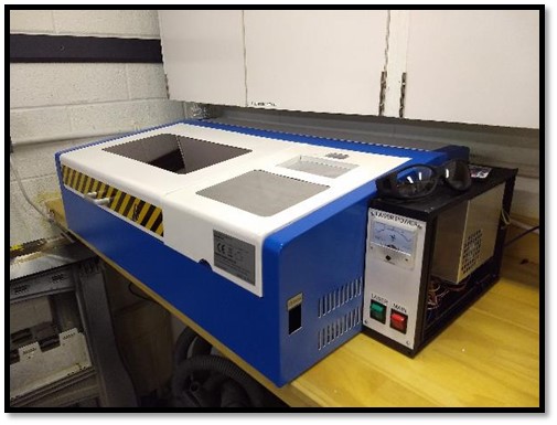
If you are reading this post, you most likely already know about the cheap 40-Watt CO2 lasers available from China, commonly referred to as K40s. There are several sub-variants of the K40 but generally they come in a white/blue or red steel case with a cutting area of about 12×8 in (300×200mm). The original Chinese manufacturers state they are for making stamps and as such the machine comes with a very weird set of features and mechanics “optimized” (very generous term) for that function.
The stock machine is capable of basic laser operations at reasonable speeds but is hamstrung by a proprietary controller board called a Moshi Board, which communicates with a computer running Corel Draw. Most K40s ship with an illegal or trial copy of Corel Draw — not something I wanted as a permanent solution. I decided right out of the gate to replace the electronics with open hardware and open software. Even after the electronics rework, I quickly became tired of the sub-par mechanics: binding and unreliable motion. After some tinkering I decided to rip the old mechanics out entirely and see how large a cutting area I could get.
Please note: the STP file (Fusion 360) is on Thingiverse — use this for reference as this guide, being done from memory, may miss a few items.
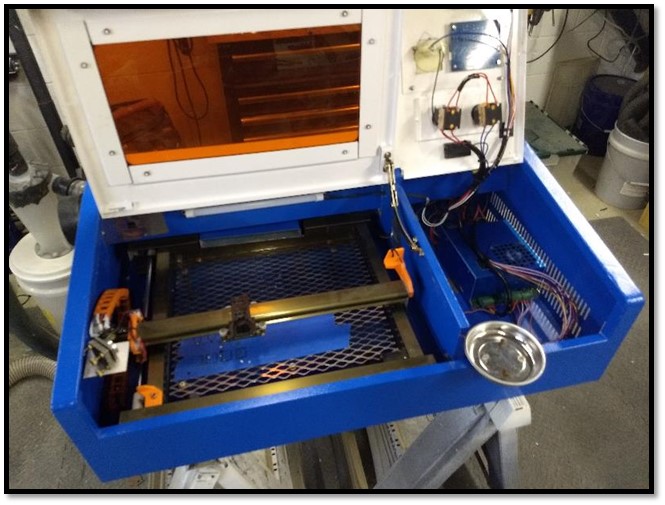
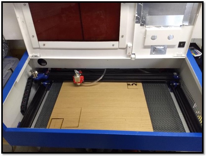
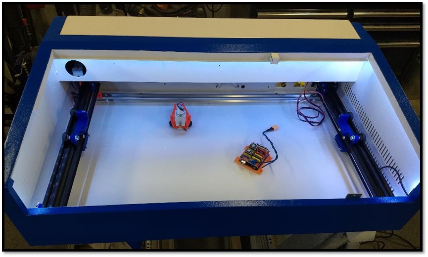
BEFORE / AFTER
Get The Files
Most of the parts required for this conversion will be 3D printed. The rest can be ordered through Amazon or Openbuilds.com. Links to many of the items used are in the Bill of Materials below.
The 3D printed parts are available on Thingiverse (Thing 3401855). I printed everything in PETG at 0.2mm layer height on an Ender 3.
The Tear Down
To start, empty the case of everything.
⛔ WARNING: This project involves high voltage, cutting tools, and lasers. Proceed at your own risk. Always disconnect mains power and allow the power supply to discharge overnight before working inside the machine.
- Take a picture of your wiring before disconnecting anything. There is a wiring diagram below, but your PSU may differ from mine.
- Unscrew all wires and remove all switches, gauges, and components from the right-hand side first.
- If your machine is like mine, there will be a RED wire running from the PSU (blue box) through the case to the back of the laser tube. You can follow online guides for changing the laser tube to disconnect it — or cut the wire halfway between the PSU and tube. The wire appears thick but has very thin conductors inside with a lot of insulation. Keep that in mind when splicing it back together.
- Remove both lids: raise them up, find the spring-loaded pin on one side of each lid, pull the pin back, and they come right off.
- Disassemble/remove the X-Y mechanism as one piece.
- Cut out the center divider and front support shelf using a grinder or rotary tool to cut the tack welds. Those I couldn’t reach I bent back and forth until they snapped.
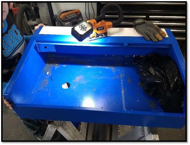
Use an orbital sander to knock down metal burrs and get the bottom of the case smooth.
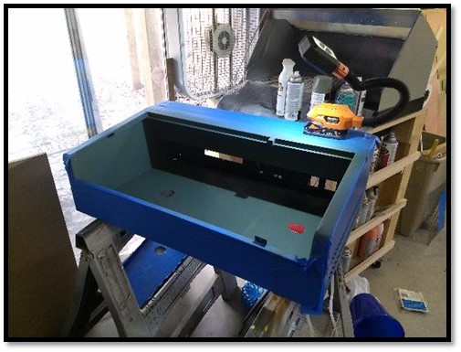
Preparation for New Install
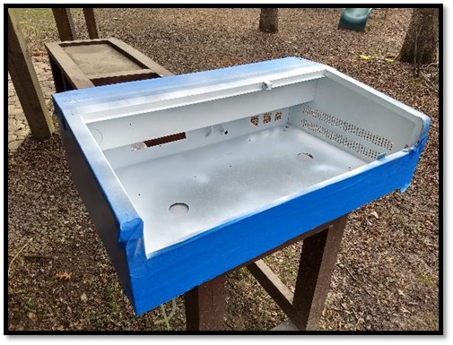
Mask everything you don’t want painted. Then give the interior of the case a good coat of Rust-Oleum primer (Amazon).
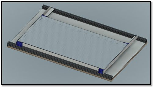
The bottom of the case is not flat or rigid — and the manufacturer added two large holes to the bottom of a laser cutter, for some reason.
To solve this, cut a piece of 1/2 in MDF to 29.75 × 18.5 in. Cut a thin piece of aluminum sheet to the same dimensions and laminate the aluminum to the MDF.
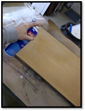
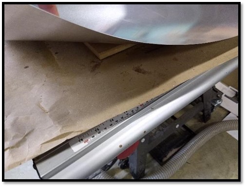
Apply several layers of Rust-Oleum satin topcoat (Amazon) to the primed case and laminated board.
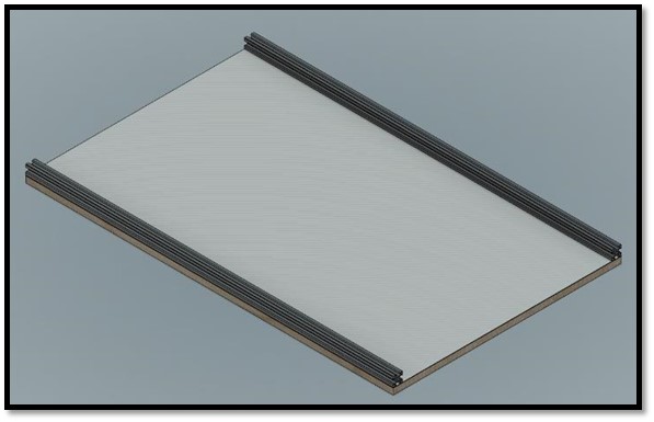
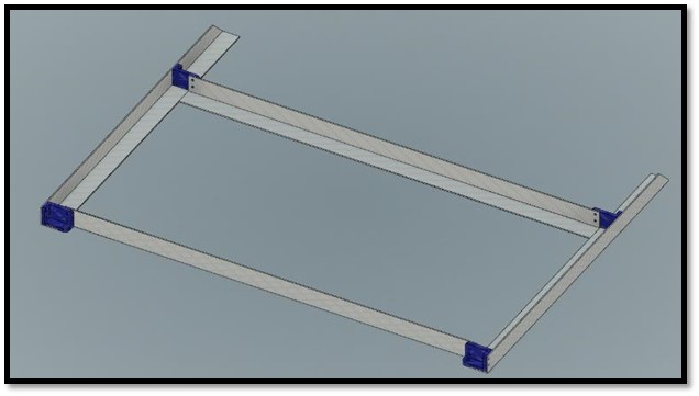
Before placing the laminated board into the case, attach two horizontal pieces of 2020 V-slot (both 29.75 in long) — one along the front edge, one along the back. Drill and countersink 4 holes along each from the bottom and attach with M5 screws and T-nuts.
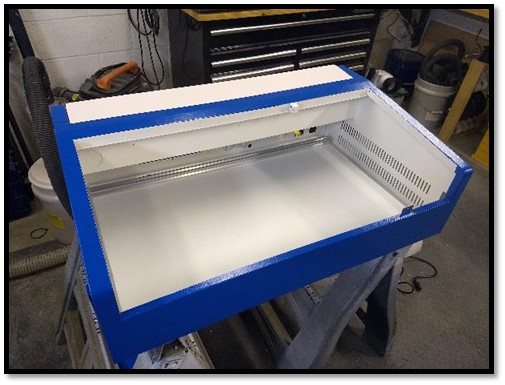
Place the board inside the case but do not secure it yet — leave flexibility until everything else is installed.
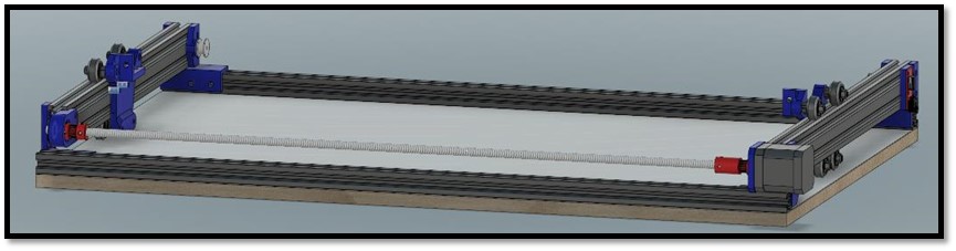
Installing the Y Axis
-
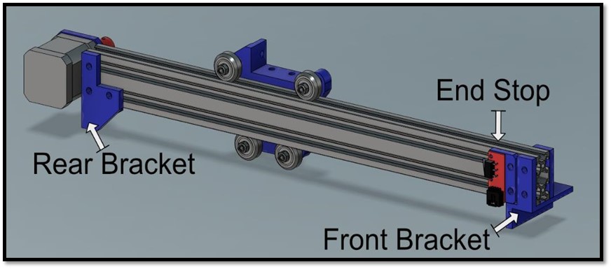
Assemble the Left Y Axis. Cut two lengths of 2040 V-slot to fit (mine were 17.75 in each). All screws M5. Use full-size V-bearings with eccentric bushings for the top two bearings, fixed spacers for the bottom two.
-
Assemble the Right Y Axis the same way.
-
Place both assemblies into the case, lining the brackets up with the front and rear 2020. Install M5 bolts with T-nuts but leave them loose for now.
-
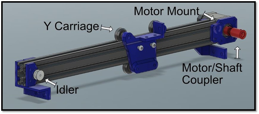
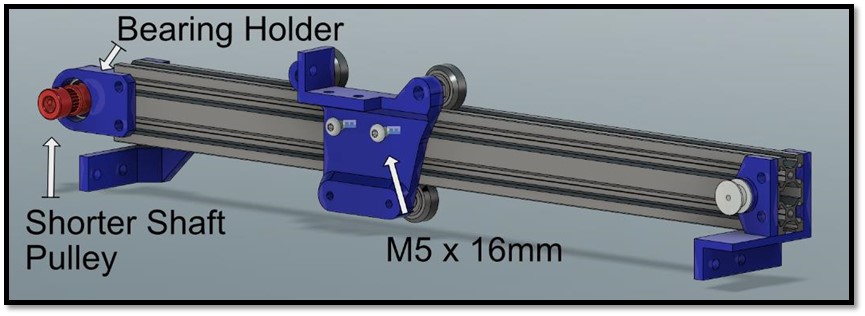
The left and right Y carriages are driven by a single motor connected in the back with a piece of 5/16 in threaded rod. Install the motor-to-shaft coupler on the left. Cut the rod to length (mine was just under 28 in — long enough to reach through the right carriage bearing mount, short enough to install with the available play). Install the right pulley.
-
Attach the belts on both carriages. I zip-tied one end of the belt to an M5 bolt on the carriage, routed it around the pulley and idler, then zip-tied the other end. Loosen the pulley slightly before routing the belt, then tension it by pulling the pulley back and securing.
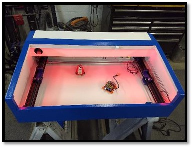
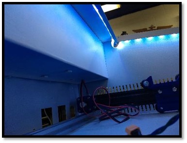
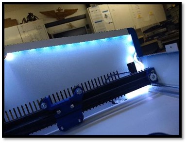
Installing Lighting
I picked up an LED strip light (Amazon) and wrapped it along the top inner lip. USB-powered, super easy, and a great addition — especially when working inside.
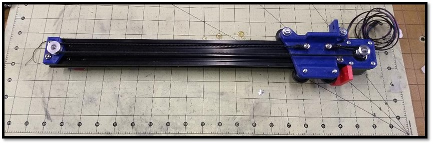
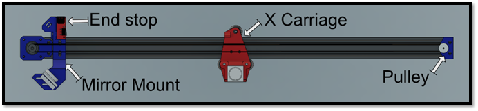
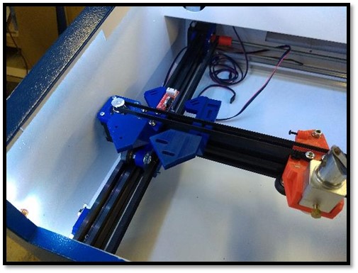
Installing the X Axis
- Cut a piece of 2040 V-slot to length (mine was 29.3 in).
- Assemble the X carriage using 3 large V-bearings with an eccentric spacer on the rear bearing. Slide onto the rail.
- Attach the motor mount (with stepper motor), pulley, mirror mount, and end stop (M3 screws).
- Attach the stock K40 Mirror Holder.
- Route and attach the belt the same way as the Y carriage — loosen the pulley to route, then tension.
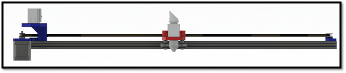
The X carriage laser head is not stock — I picked up a solid aluminum aftermarket head with an adjustable-height lens and air-assist assembly. This allows ±10mm height adjustment and means I can use a static cutting bed that never needs to move.
Place the X axis assembly into the case and attach it to the Y carriages with M5 screws.
The Bed
I thought about the cutting bed for a long time. My first iteration used a metal grate from the hardware store — it worked but left burn marks where the laser cut through. Professional machines use aluminum honeycomb, so I found some at a reasonable price on Amazon. Even at 1 in thick, it still flexed slightly and needed support on all sides.
Solution: four lengths of 1 in aluminum angle iron:
- 2 × 22.9 in
- 2 × 18 in with a 45° cut off one end
3D print the corner pieces, use them as a drill guide, tap the aluminum, and secure with #4-40 × 0.25 in screws (or M3 / M2.5). The whole assembly slides into the case and secures in the front with M5 bolts; the back rests on the rear 2020 V-slot.
Secure the Assembly
Slide the assembly all the way forward, then as far left as possible — leaving about 1/4 in clearance between the outer case wall and the X-axis motor. Run the head around by hand to verify the position makes sense, then use self-tapping screws up through the bottom of the case into the 1/2 in MDF sheet. (This is why I assembled on sawhorses — I anticipated needing to work from below.)
Lid
Reinstall the lids and bolt the two halves together using an existing center hole. Cover the now-exposed holes in the lid with leftover aluminum sheet, secured with aluminum tape.
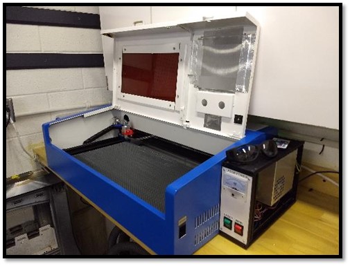
Electronics
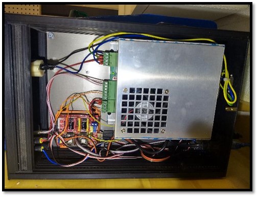
There is no longer any room for the electronics inside the case, so I used a salvaged metal enclosure mounted to the right side of the machine (visible in the photos above).
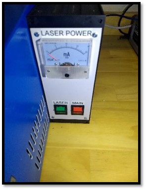
New face plate: I cut a face plate from sheet plastic by hand, adding an ammeter, a main power switch, and a laser power switch. The switches were salvaged from the original unit. The ammeter was an Uxcell 0–20mA Analog DC Current Panel Meter (Amazon).
Drill a 1 in hole in the upper right corner of the enclosure into the laser tube area to route the laser power wires. Drill another hole in the lower right corner for the motor and end-stop wires. Secure the PSU (I removed the blue film — now silver) and the Arduino Uno with GRBL shield.
Wiring (many thanks to Don’s Things for his extensive research on these units):
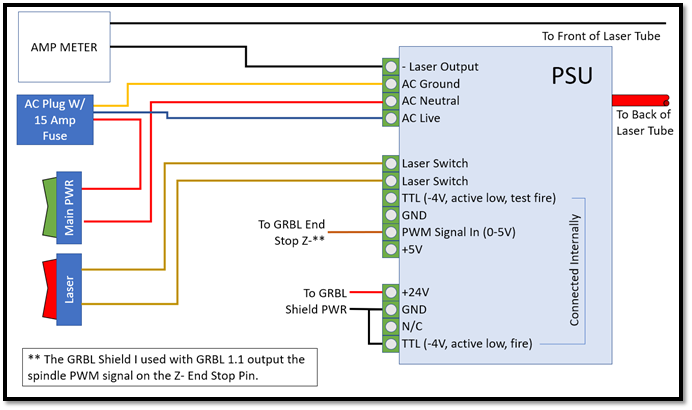
Wiring Diagram
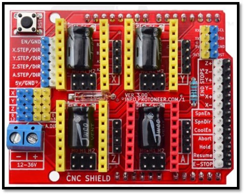
GRBL Shield
Note: In GRBL 1.1 the PWM signal is on the End Stop -Z pin, not Spindle Direction or Spindle Enable. I also tied the Laser Fire pin straight to ground to reduce complexity — I keep the laser switch off until just before running a program and always turn it off before opening the lid. Consider adding a lid-open safety interlock as an upgrade.
End stops and motors are wired per the GRBL shield markings. Install stepper drivers in the X and Y axis slots and tune accordingly.
Software and Firmware
GRBL is open-source firmware for Arduinos that controls a CNC via serial port. Download from GitHub (gnea/grbl). The wiki has extensive configuration documentation.
GRBL runs on an Arduino Uno; the GRBL Shield sits on top of the Uno to simplify wiring. Any G-code sender will work; my two favorites are:
Configuration is refreshingly simple compared to Marlin — most 3-axis setups need very few source changes. I only modified the homing cycles since my machine has only X and Y axes:
// Changed from:
#define HOMING_CYCLE_0 (1<<Z_AXIS)
#define HOMING_CYCLE_1 ((1<<X_AXIS)|(1<<Y_AXIS))

// To:
#define HOMING_CYCLE_0 ((1<<X_AXIS)|(1<<Y_AXIS))
//#define HOMING_CYCLE_1 ((1<<X_AXIS)|(1<<Y_AXIS))
After uploading the firmware via Arduino IDE, enter the following settings via the Arduino Serial Monitor (type each as $N=value, e.g., $0=10). Type $$ to verify all values afterwards.
GRBL Configuration Settings
| Setting | Description | Value |
|---|---|---|
| $0 | Step pulse, µs | 10 |
| $1 | Step idle delay, ms | 255 |
| $2 | Step port invert mask | 0 |
| $3 | Direction port invert mask | 0 |
| $4 | Step enable invert | 0 |
| $5 | Limit pins invert | 0 |
| $6 | Probe pin invert | 0 |
| $10 | Status report mask | 16 |
| $11 | Junction deviation, mm | 0.010 |
| $12 | Arc tolerance, mm | 0.002 |
| $13 | Report inches | 0 |
| $20 | Soft limits | 0 |
| $21 | Hard limits | 0 |
| $22 | Homing cycle | 1 |
| $23 | Homing dir invert mask | 3 |
| $24 | Homing feed, mm/min | 100.000 |
| $25 | Homing seek, mm/min | 750.000 |
| $26 | Homing debounce, ms | 100 |
| $27 | Homing pull-off, mm | 1.000 |
| $30 | Max spindle speed (laser %), RPM | 1000 |
| $31 | Min spindle speed, RPM | 0 |
| $32 | Laser mode | 1 |
| $100 | X steps/mm | 80.000 |
| $101 | Y steps/mm | 80.000 |
| $102 | Z steps/mm | 34.000 |
| $110 | X max rate, mm/min | 1500.000 |
| $111 | Y max rate, mm/min | 1500.000 |
| $112 | Z max rate, mm/min | 300.000 |
| $120 | X acceleration, mm/sec² | 300.000 |
| $121 | Y acceleration, mm/sec² | 300.000 |
| $122 | Z acceleration, mm/sec² | 10.000 |
| $130 | X max travel, mm | 609.000 |
| $131 | Y max travel, mm | 304.000 |
| $132 | Z max travel, mm | 300.000 |
For full documentation on each parameter see the GRBL v1.1 Configuration Wiki.
Bill of Materials
The following is as complete a BOM as I can generate. My build was completed mostly with parts I had on hand from other projects — I spent a total of about $5 in new hardware.
Electronics BOM
| Item | Qty | |
|---|---|---|
 | CHENBO Endstop Mechanical Limit Switches | 2 |
 | TecUnite 3-Pin Stepper Motor Extension Cables | 1 set |
 | Usongshine NEMA 17 Stepper Motor 17HS4401S | 2 |
 | Uxcell 0–20mA DC Panel Ammeter | 1 |


